What is an Evaporative Condenser?
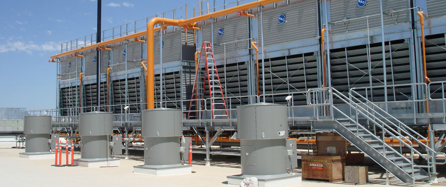
Designed for industrial refrigeration, industrial processes, and HVAC, BAC’s evaporative condensers lower system condensing temperatures thereby reducing compressor horsepower, saving up to 15% energy compared to traditional air-cooled systems. This cost-effective cooling solution condenses refrigerant vapor in a coil that is continually sprayed with water. As the water evaporates, fans reject this heated vapor to the atmosphere.
Principle of Operation
The vapor to be condensed is circulated through a condensing coil, which is continually wetted on the outside by a recirculating water system. Air is pulled over the coil, causing a small portion of the recirculating water to evaporate. The evaporation removes heat from the vapor in the coil, causing it to condense.
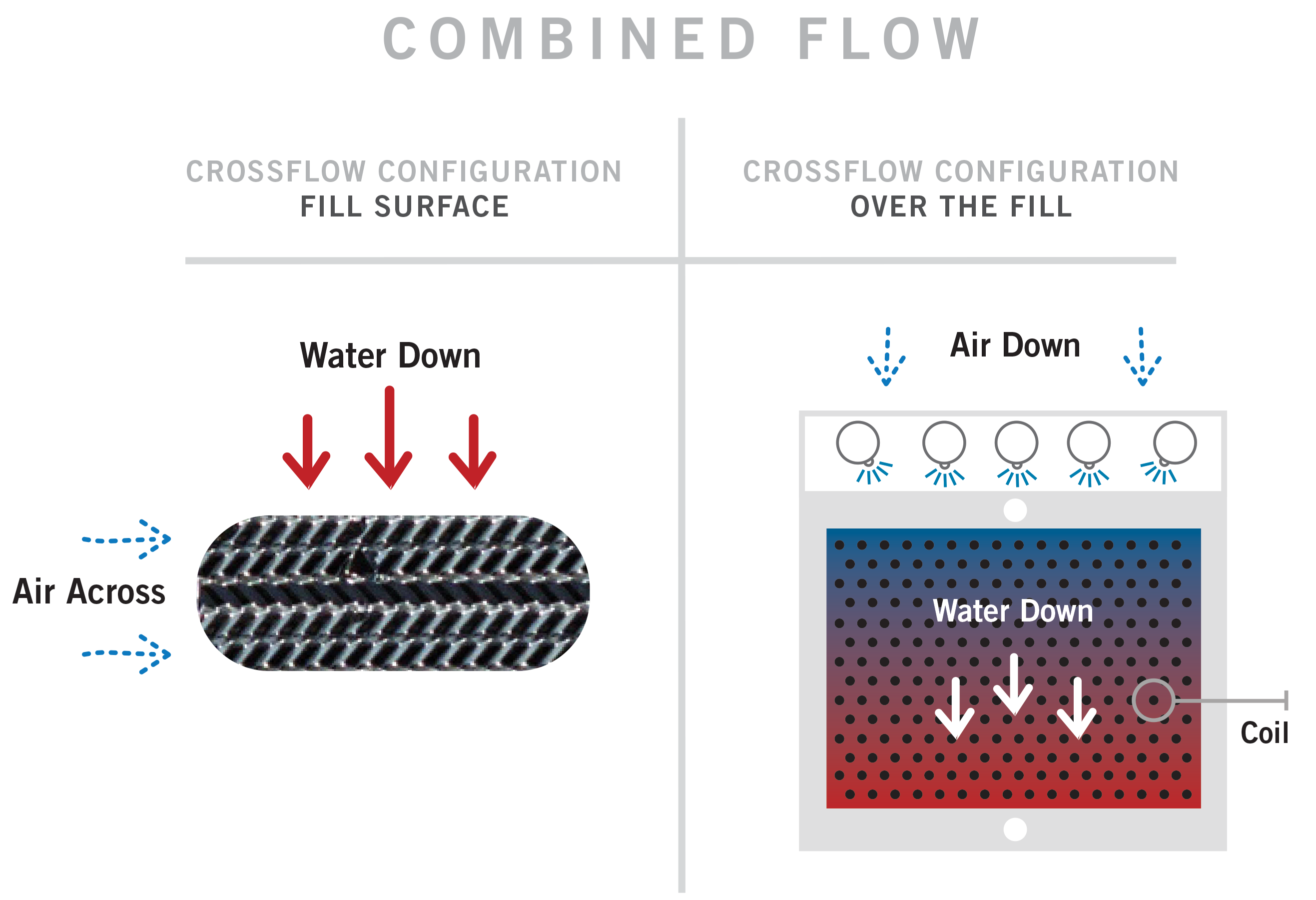
Combined Flow Configuration
BAC manufactures two types of evaporative condensers: combined flow and counterflow. Combined flow is the use of both a condensing coil and fill surface for heat transfer in an evaporative condenser. The addition of fill surface to the traditional evaporative condenser design reduces evaporation in the coil section, reducing the potential for scaling and fouling. BAC’s combined flow evaporative condensers utilize parallel flow of air and spray water over the coil, and crossflow air/water flow through the fill surface. In parallel flow, air and water flow over the coil in the same direction. In the fill section of BAC’s combined flow evaporative condensers, air and water interact in a crossflow configuration: water flows vertically down the fill as air flows horizontally across it.
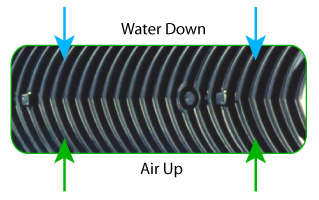
Counterflow Configuration
In a counterflow evaporative condenser design, the flow of the air is in the opposite direction of the spray water. In BAC’s counterflow evaporative condensers, air travels vertically up through the unit while the spray water travels vertically down over the coil. The flow of air through most factory assembled evaporative condensers is provided by one or more mechanically driven fans.
Fan System
-
Axial Fan
-
Centrifugal Fan
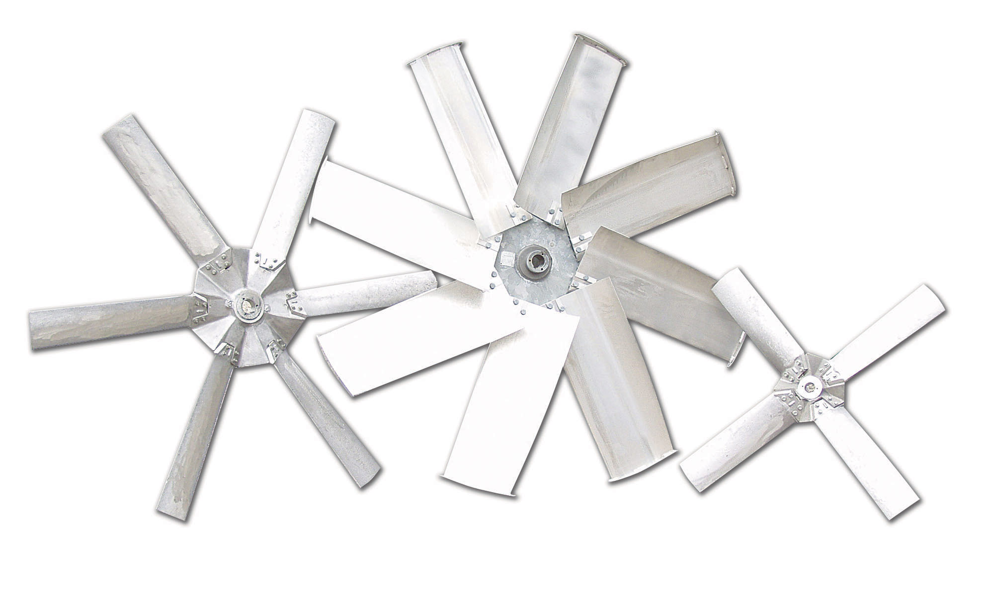
The fan(s) may be axial or centrifugal, each type having its own distinct advantages. Axial fan units require approximately half the fan motor horsepower of comparably sized centrifugal fan units, offering significant life-cycle cost savings.
Induced Draft
The rotating air handling components of induced draft equipment are mounted in the top deck of the unit, minimizing the impact of fan noise on near-by neighbors and providing maximum protection from fan icing with units operating in sub-freezing conditions. The use of corrosion resistant materials ensures long life and minimizes maintenance requirements for the air handling components.
Forced Draft
Rotating air handling components are located on the air inlet face at the base of forced draft units, facilitating easy access for routine maintenance and service. Additionally, location of these components in the dry entering air stream extends component life by isolating them from the corrosive saturated discharge air.
Reduces Fouling Tendency
Advanced coil technology, applied on CXV Evaporative Condensers, is used to reduce the tendency to accumulate fouling and scale on the coil’s exterior surface. Four facets of the unique product design contribute to the reduced tendency for fouling:
The Air and Water Flow in a Parallel Path
Better water coverage over the coil is maintained because the air and spray water flow in a smooth, parallel, downward path over the coil. With this parallel flow, the spray water is not stripped from the underside of the tubes by the upward air flow, as on other, conventional designs. This eliminates scale-producing dry spots on the coil.
Increased Water Flow Over the Coil
The spray water flow rate over the coil plan area is more than twice that of conventional units. This heavy coverage provides continuous flooding of the primary heat transfer surface for decreased fouling potential. Improved spray water coverage is provided at no increase in pumping horsepower due to the unique heat transfer system of the design.
Evaporative Cooling Occurs Primarily in the Fill
CXV models incorporate combined flow technology, using both primary and secondary heat transfer surfaces. The primary heat transfer surface is the serpentine coil, which is the most important and expensive component in the unit. In BAC’s combined flow design, more than 80% of the latent heat transfer occurs in the secondary surface, PVC cooling tower fill , effectively moving the evaporation process away from coil. The coil is protected from detrimental fouling and scale since it relies primarily on sensible conduction/convection heat transfer and, therefore, is less susceptible to scale formation than are other designs that rely primarily on latent (evaporative) heat transfer.
Colder Spray Water
Spray water at a colder temperature has a lower propensity to form scale because scale-forming compounds remain in solution, rather than deposit as solids on the coil exterior surface. Spray water flowing over the coil is commonly 6°F to 8°F colder than on other designs due to the addition of the secondary heat transfer surface. Colder spray water alone typically reduces the scaling potential* by 25% compared to other designs. This is over and above the fouling reductions achieved by the first three factors described above.
*Using Langelier Index